Tearing Into a Linear GD004-Z
•
So after 2 years, my z-wave garage door opener bit the dust. I’m a little disappointed because I really feel like it should have lasted longer. As I wait for the other one to arrive, I decided it would be fun to start pulling apart the existing on (it’s broken, right?).
I should note that when I say “broken” I mean that it will no longer lift and lower the associated garage door. The system continues to generate beeps, but the LED never flashes and the door fails to open. Most of my research into the forums seem to indicate this is a common problem and the only resolution is to have the vendor send you a replacement one (so far, I think that’s still probably the best path).
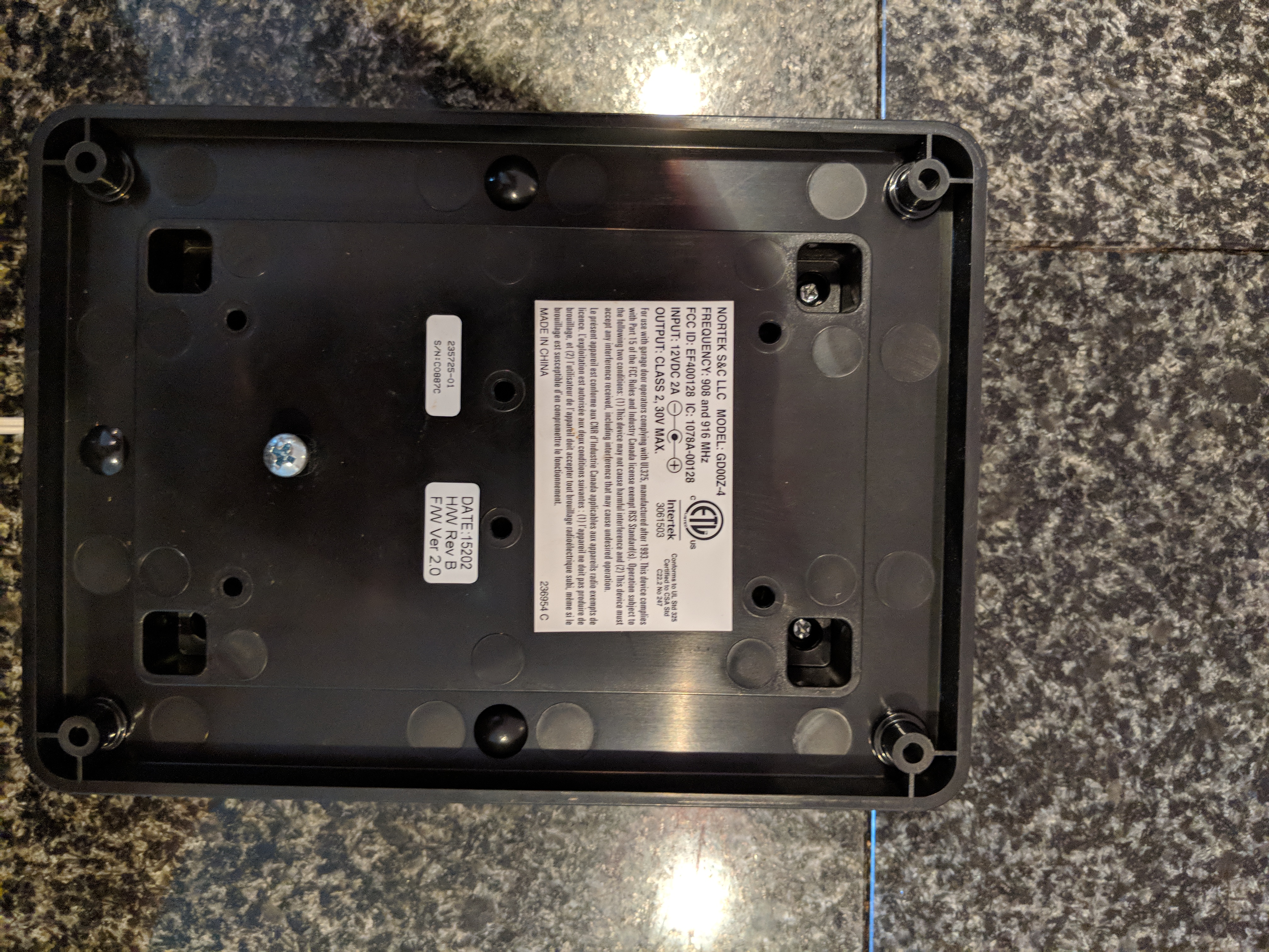
First things first, let’s open it up and see what we have. Removing 4 screws on the back is easy enough:
And reveals the following layout:
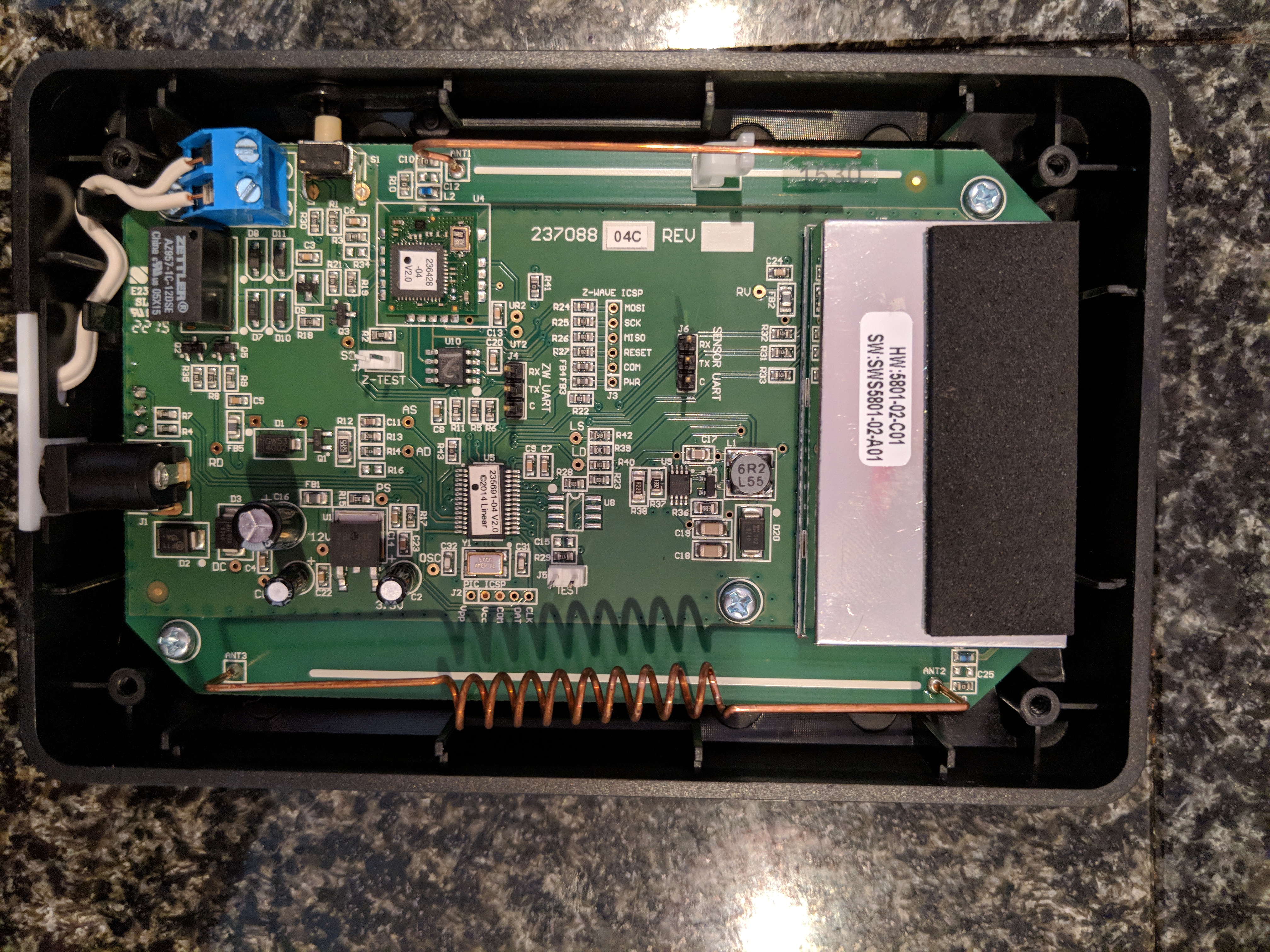
My interest is instantly drawn to the SENSOR UART pins (populated!!!) as a first place to go. If you’ve ever read anything from Embedded Device Hacking, many hardware manufactures will attach associated serial ports to these sytems for testing and debugging access. It appears the same is true for this manufacture.
Initially, I went for broke, and just dropped my Bus Pirate on to see if I’d get lucky:
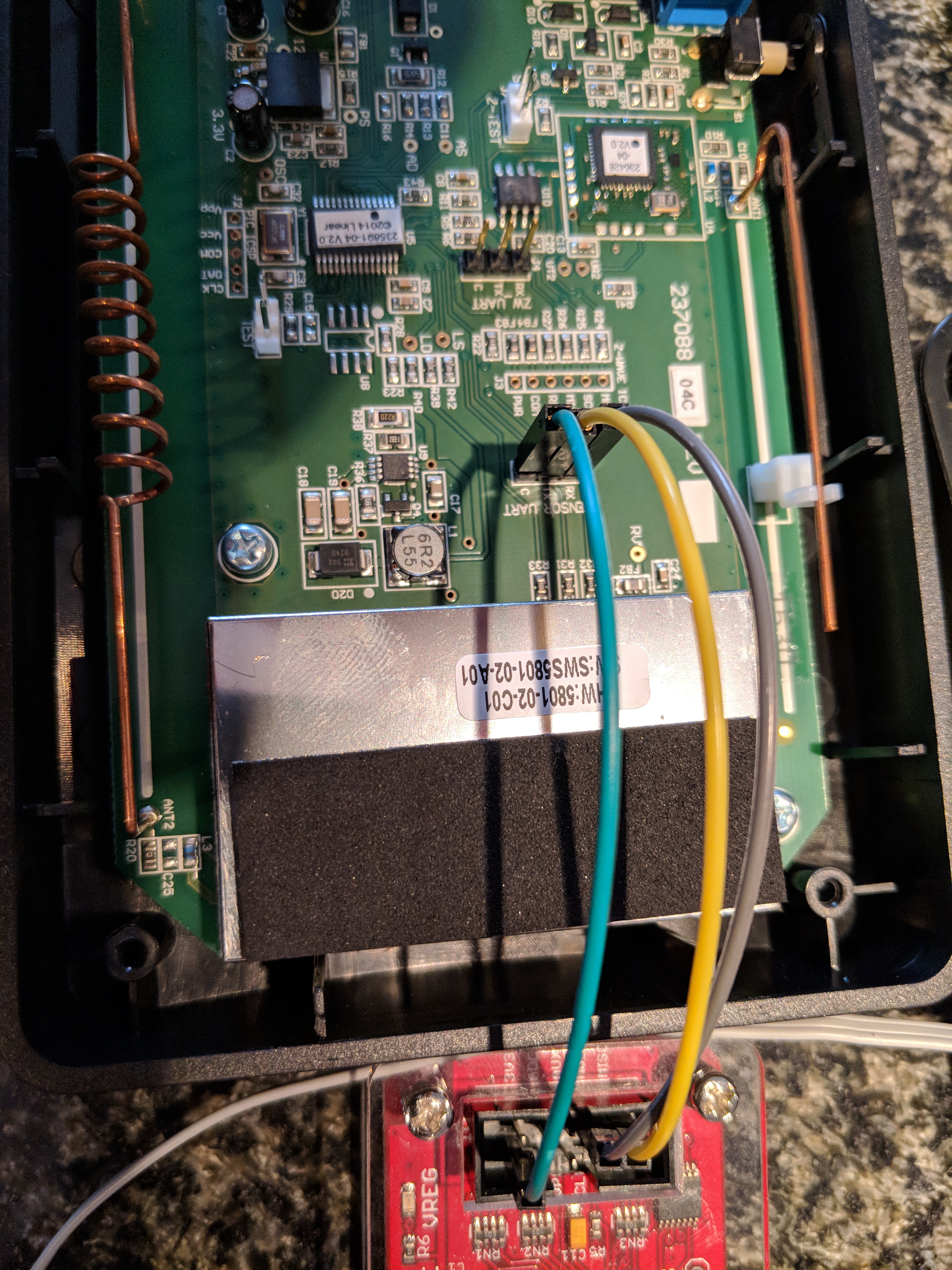
No such luck … nothing back, no luck with auto baudrate detection … nothing. So it was time to break out the scope. I’ve had an OpenScope MZ that’s been begging to cut it’s teeth on something so put the oscillicope on the TX pin and futzed with trying to get something (anything really) out of the system for an hour or so with no luck. It was about this time I noticed that my red power LED was no longer working and I couldn’t seem to deterime why (everything else seemed to have power on the board).
At this point, I turned to looking at the two jumpers on the sytem. Fortunately, there were only two paths to brute force on it, and jumping both of them resulted in actually getting some reading over the scope
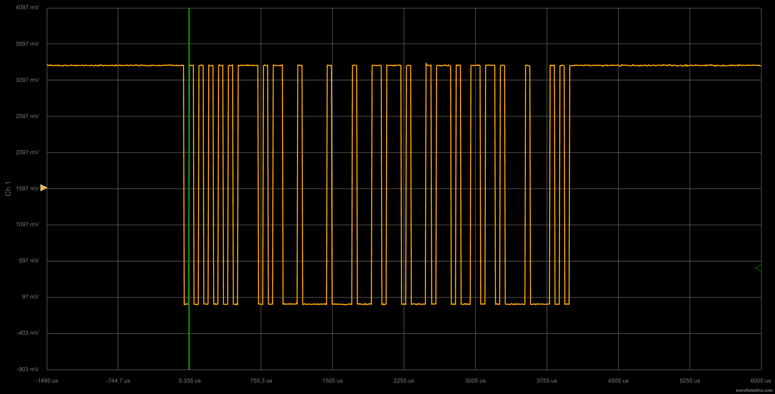
Huzzah! That looks like some serial data if I’ve ever seen it. Now that I’d managed to figure out my combination, I went back to the bus pirate and performed an auto baud rate analysis and it arrived at 19200. Time to fire up some fun with the live serial port monitor; the associated BP settings are:
| setting | value |
|---|---|
| mode | UART |
| bps | 19200 |
| bits & parity | 8, None |
| stop bits | 1 |
| rx polarity | 1 |
| output | 2 (normal) |
And finally…
Well, that’s neat. Pushing the button in test mode results in the following (noisy) output:
LEDs TEST
LEDs TEST DONE
WARNING LAMP TEST
ADC:0x0e18 - WARNING LAMP SENSE -- FAILED
WARNING BUZZER SOUND
ADC:0x0738 - WARNING BUZZER SENSE -- PASSED
RELAY TOGGLE
WALL SWITCH SENSE -- WALL SWITCH IS PRESSED
WALL SWITCH SENSE -- WALL SWITCH IS PRESSED
R345 interface test started.
R345 RECEIVER INTERFACE TEST -- FAILED
Z-Wave interface test started.
Z-WAVE MODULE INTERFACE TEST -- FAILED
Sadly, test mode is boring and basically just a continual loop of doing the above things. I should note that I’m not 100% certain of the accuracy of the above output - but if it’s right, it would clearly explain why my controller doesn’t work in any useful fashion. Another interesting note is the R345 RECEIVER INTERFACE listed. I’d venture a guess that this is the communication between the controller and the door open/close sensor.
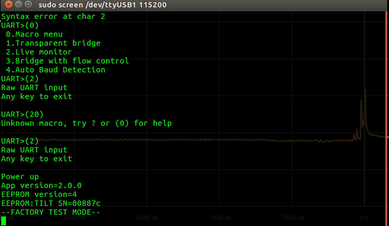
So leaving the BP on and rebooting the system with out the jumpers in place, we get the following:
UART>(2)
Raw UART input
Any key to exit

Power up
App version=2.0.0
EEPROM version=4
EEPROM:TILT SN=00887c
Application firmware by Siva Kathan, Martin Mucciarone, and Mi Jin Park. Z-Wave firmware by Steve Boyle.
The “firmware by” line is only printed after holding the associated button on the board for about 10 seconds and then releasing once you get to a series of beeps that follow in a row.
I also tried putting the BP in transparent bridge mode to see if there was any way to interact with the system, but sadly, it does not appear that there is a direct method of input at this point in time. I’ve considered pulling off the associated firmware images via the ICSP headers (there’s one for PIC and one for Z-WAVE), but that will be an exercise for a later date since this damn thing keeps beeping and there’s only so much I can stand.